Double Panels#
Connections (Frame type)#
In a double panel wall, there are various ways in which the two sides of the wall can be connected. These connections provide a path for the transfer of vibrational energy which is then radiated as sound. To model the performance of double panel walls therefore it is important to model the connections as accurately as possible. The most common connection is a timber stud frame to which linings are attached on each side. This forms a line connection between the panel. When modelling this type of wall in INSUL one should select "Timber stud". You can filter the frame/connection type by categorising into timber, steel or masonry type connections.

Although there are many types of connections available in INSUL (currently 19 different wall connection types and 8 ceilings/floor types) there will be connections that the user comes across that are not within these types. In many cases, it is possible to choose a connection that is almost equivalent.
Info
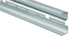
The acoustic stud type might be used for the acoustic stud offered by different manufacturers such as:
- Knauf Acoustic C studs
- Winstone Wallboards Quietstud
- Peer Acoustic Stud
- Siniat GETEC
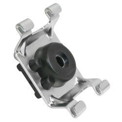
The rubber isolation clip is a good representation of the RSIC clip from PAC International, but also the Pliteq GenieClip™ and the Kinetics IsoMax resilient sound isolation clips.
For ceiling/floor connections it has been found that very high-performance spring hangers (with a natural frequency of 4 Hz or less and incorporating both steel and neoprene isolation elements, for instance, Kinetics ICC-50 spring hangers) can approach the performance of Separate joists, demonstrating that the isolator is very effective at reducing the transmission of vibration to negligible levels. Similarly, the Kinetics IsoGrid ceiling hanger can be modelled by the Resilient clip or channel connection, and the Kinetics Super-Compact Ceiling Hanger Model KSCH is able to be modelled by the Suspended light steel grid connection.
It should be noted that the Double timber stud, Double steel stud, and None type of connections are the same internal model, that is no structural transmission of vibration between the panels and only differ in the picture that is displayed. However, the Double Masonry connection models some trace of the structural path that must exist in most modern laboratories and represents the performance you will achieve for 2 heavy walls separated by an air gap in a high-quality test laboratory. Clearly, in most field situations there will be more flanking transmission and this must be allowed for.
It is worth discussing the Bonded Insulation connection or frame type. This is provided to model proprietary insulated plasterboard panels such as:
- Calibel
- Rockwool International LabelRock
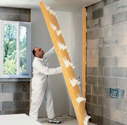
These boards have a mineral fibre panel bonded to the back of a gypsum plasterboard panel. Note at this stage the Bonded Insulation connection or frame type should not be used for insulated panels using PIR as the insulation medium.
Cavity Infill#
Benefits of cavity infill
In a cavity wall, the sound will be transmitted from the source side into the cavity. If the cavity is empty then the sound will build-up inside the cavity and this reduces the performance of the overall wall. This is much like an empty room with no carpet or furnishings, the sound reverberates and echoes around the space. By placing an absorber into the cavity this build-up is reduced and the performance of the wall is improved.
The effect is most noticeable when the two sides of the cavity wall are completely separated because then the only transmission path through the wall is through the air in the cavity. In walls that have solid connections between the two sides (such as with a common stud wall) the structural path by the connections/studs will short circuit the cavity, and the influence of the cavity infill or absorption is not so great.
For double-stud walls which have very few connections, the cavity absorption can improve the overall sound transmission rating by 8 to 10 dB, compared to an empty cavity. For simple single stud or common stud walls, the improvement might only be 3 dB.
The improvement is proportional to the acoustical performance of the cavity infill or absorber. Thicker and denser absorbers will perform better. However, there is a low of diminishing returns and even for double-stud walls, there is often only a small benefit to be gained by increasing the cavity absorber above about 30 kg/m3 and 100 mm thickness.
A further benefit of using a cavity absorber is the reduction in the resonance frequency of the cavity wall. Typically a plasterboard wall will have a resonance frequency in the region of 100 Hz, and this can be reduced by about 20% by placing an absorber in the cavity. This will improve the low-frequency performance of the wall. From version 8.0 onwards this shift in resonance frequency is modelled more accurately by modelling the cavity as an equivalent fluid using the properties predicted from the flow resistance of the absorber. Thus as the flow resistivity of the cavity infill is increased the resonance frequency will decrease (in previous versions it was either adiabatic (no infill) or isothermal (infill present) with nothing in between).
Modelling cavity infill
From INSUL version 5, INSUL can predict the performance of double panel walls if there is an absorptive blanket in the cavity between the panels or if the cavity is empty. The type of absorptive blanket can be selected from the drop-down list.
From INSUL version 5.3, the thickness of the absorptive material can be altered by entering the new thickness in the field to the right of the absorptive material selection list.
From INSUL Version 8.0, improvements have been made to the accuracy of the prediction, based on empirical information from NRC tests (IRC-IR-693 1995 Sound Transmission Through Gypsum Board Walls: Sound Transmission Results)

The absorptive blanket can be fibreglass, Rockwool, polyester fibre, wool, or open-celled plastic foam. Additional materials can be entered using the Materials Editor The information required is the description of the material, its thickness and its flow resistivity. Because the method of modelling the effect of different materials is quasi-empirical it should be used within limitations.
Caution
Do not use materials thinner than 25 mm or thicker than 200 mm and do not use materials less than 500 Rayls/m or more than 60,000 Rayls/m.
Flow resistivity information can be found either from the Manufacturer of the acoustic blanket or by relating the flow resistivity to the density using relationships such as given in Beranek's (1971) Noise and Vibration Control Chapter 8. In version 8.0.12 there is a calculator to estimate the flow resistivity for several common material types based on the density of the absorber. If in doubt you can send us a description of the product and we can attempt to work out data.

Tip
A special case is double glazing for which INSUL has a special empirical routine.
The absorptive blanket has several related effects, it dampens the mass-air-mass resonance, it dampens cavity modes which otherwise provide coupling between the two panels, and it reduces the reverberation in the cavity thus reducing the build-up of sound in the cavity (One might say these are just different ways of looking at the same physical effect).
Timber Studs#
A common form of construction is to use timber studs to make a framework and line either side with plasterboard or similar panel materials. Timber studs are usually 100 x 50 mm in cross-section but can be smaller or larger depending on structural requirements. Timber studs act as very stiff, light connections between panels and can be modelled to acceptable accuracy as line connections between panels.
Thus the frame/connection when the Wall tab is selected which is named "Timber stud" uses line connections between panel 1 and 2 to calculate TL.
Tip
Should you need to model other forms of construction that rigidly connect between two panels along lines, then you can use this option.
From this discussion, it is apparent that this option is only valid where the panels are rigidly connected and the panels make a connection along with the whole length of the stud. If a resilient element is placed between the stud and the panel then the TL will, in general, be increased above what is predicted from line connections.
There are different construction methods for reducing or eliminating the structural transmission through the studs, some common forms are:
Double Studs#
Double studs provide the ultimate in performance for framed partition walls. They are constructed by erecting two separate frames, usually 25 mm apart, and lining the outside of each frame typically with 1 or 2 layers of plasterboard. Because there is no physical contact between each side of the wall, the only transmission path is via the air cavity and provided this has an absorbent blanket very high TL's can be achieved. In practice flanking transmission would often prevent the very high TLs predicted at high frequencies, but in extreme cases where measures have been taken to prevent flanking TL's of 60-70 dB at 1 kHz and above can be achieved (e.g. adjacent rooms on concrete floating floors).

Double-stud wall showing an arrangement of studs.
Resilient Connections#
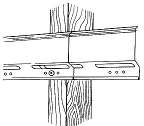
Resilient rails
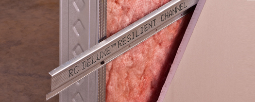
Resilient rails are used in partition walls to increase the TL. They are normally fixed to timber studs, with the wall or ceiling linings fixed to the resilient rail rather than directly to the stud. The function of the rail is to prevent direct vibration transmission via the stud by acting as a soft spring between lining and stud. Resilient rails are usually steel channels folded in such a way as to be quite springy. They are normally fixed in horizontal lines at 600 mm centres.
Caution
They are very easy to install wrongly however and with inexperienced workmen, the chances are that the wall will not achieve the predicted or lab performance. The user should be very careful that the properties of the resilient rail are similar to the well known USG resilient rail, as there are several copies of this used which do not provide the same degree of isolation.
Sometimes resilient rails are used on both sides of a wall. However, the result is only slightly better than using on only one side and so there is little to be gained. Be wary of using the resilient channel option for any brands that are not of identical design to the Detrich RC deluxe resilient Channel (see below).
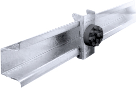
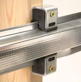
Rubber isolation clips
Improved performance can be achieved with a metal bracket incorporating a rubber or neoprene isolation element. A good example is the RSIC-1 clip from Sound Isolation System Ltd. This fixes to the stud or joist and holds a metal channel to which the wall lining is screwed. Another example is the Sound Isolation clip from Kinetics, and another one is the Genie Clip from Pliteq. The rubber or neoprene ensures a high degree of isolation from the wall frame and sound insulation can approach a double frame wall performance. It is also much more reliable than resilient rails.
Ceiling supports
In the case of a ceiling, it is also possible to introduce a resilient element. Normal practice is different in different countries. In North America, it is common to use a 13 mm resilient metal channel. In Australia, it is common to use resilient clips (e.g, Rondo or Gyprock or RSIC) while in New Zealand the Gib Ceiling batten can be used to provide isolation. The RSIC clips are also able to be used in a ceiling and as in a wall, they provide a high degree of isolation.
Steel Studs#
Steel studs are used to construct framed partition walls. In some countries, they are used extensively almost to the exclusion of timber studs. They generally provide much higher sound transmission loss performance than timber studs because they are far less rigid than timber studs. Typically steel studs would be C or Z shaped in cross-section, made of 0.55 mm thick steel and come in various cross-sectional widths (51, 63, 92 mm wide). From the test data that is available steel studs seem to work about as well as a resilient rail.
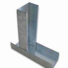
From INSUL version 5.5, there is an option to predict steel studs with a resilient rail has been added. This predicts better performance at higher frequencies as the degree of decoupling between the two leaves increases.
From INSUL version 6.1, there is an "acoustic stud" option for frame type has been added. This should predict the performance of new steel studs that are specifically designed to improve sound transmission loss of plasterboard walls using steel studs (e.g, from Knauf, Lafarge or Winstone/Rondo).
From INSUL version 7.0, there is an option to predict CH studs has been introduced. These are typically robust steel studs used to form Shaft risers in multi-storey buildings and are shaped somewhat like a C on top of an H, hence the name. Typically, the stud will accommodate a 25 mm thick board which provides the fire rating required for shafts.
From INSUL version 8, the options have been expanded to include steel studs of 0.55 mm (26 gauge) or 1.0 - 1.6 mm (20 - 16 gauge) steel thickness.
Staggered Studs#
A question often asked is:
"When a construction is calculated with double (wood) studs or staggered studs the results change dramatically. There isn't much constructional difference between double studs or staggered, both have no contact from the inside panel to outside. So should not the difference in acoustical terms should be comparable?"
The answer lies in the detail of their respective construction. A staggered stud wall usually has a common top and bottom plate (see picture below), so there is a direct bridge between the sides of the wall. INSUL models this as a line connection at 2.7 metres separation. However, a double-stud wall has two completely separate rows of studs, and so no structural connection between the two sides and therefore a much higher sound insulation performance.

Staggered Stud wall construction
Double-stud wall construction
Z Girt#
A Girt is a horizontal structural member in a framed wall (The corresponding member in a roof is a purlin).
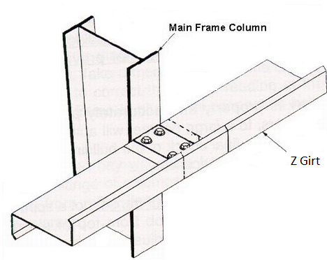
Z Girts are used in many countries in the construction of industrial buildings that are typically clad with profiled steel sheets. Z Girts are typically steel of 1.2 mm thickness, bent to a Z profile and fastened horizontally to steel frames, with the weatherproof cladding fixed to the Girt.
The Z Girt modelled in INSUL is of 1.2 mm thickness. If a girt has a steel thickness greater than this, then INSUL may over-predict its performance and it may be better to use a solid connection (eg timber stud). This connection may also be used for steel purlins of 1.2 mm thickness.
Butterfly Ties#
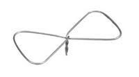
Butterfly ties are steel wires used to structurally connect separate masonry walls. Their name derives from their shape and they are predominantly used in the United Kingdom. They are laid between brick courses across the gap between the two walls.
Suspended Ceiling Steel & Neoprene Hanger#
Laboratory tests show that the Kinetics ICC-50 Deck-Suspend Ceiling Hangers give isolation equivalent to a separate joist construction. That is the ultimate isolation and is rarely seen in an acoustic isolator.
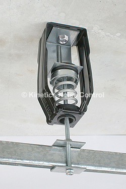
For modelling floor/ceiling constructions using this hanger use the "Steel Spring Hanger". Similar units from Mason Industries, for example, would be expected to perform similarly.
Double Masonry#
This connection type has been added to model the laboratory performance of double masonry walls that have no apparent connections between them. This option is preferred to either "none" (or "double-stud") for double masonry walls as based on what limited laboratory data we have the "none" option will significantly overestimate the transmission loss. While every effort is made in laboratory design to eliminate flanking paths, it appears that it is very difficult (at least for masonry walls) to eliminate all traces of flanking. This flanking will generally be paths involving the test walls, so the ultimate flanking of the laboratory may well be greater than the measured performance with masonry walls. Masonry walls are heavy and must be well supported and are well-matched in impedance to the laboratory structure, so there will be some structural transmission between the two masonry walls via the laboratory structure as well as the airborne transmission across the gap between the walls. The structural path has been modelled for a modern laboratory, and may overestimate the transmission loss measured in older laboratories which were constructed with less protection.
Caution
Of course in a field situation flanking will be even more difficult to control than in a laboratory, so the prediction by INSUL must be used with caution and all possible flanking paths are taken into consideration in the calculation of room to room transmission.